
A Brief History of the RM Alternator.
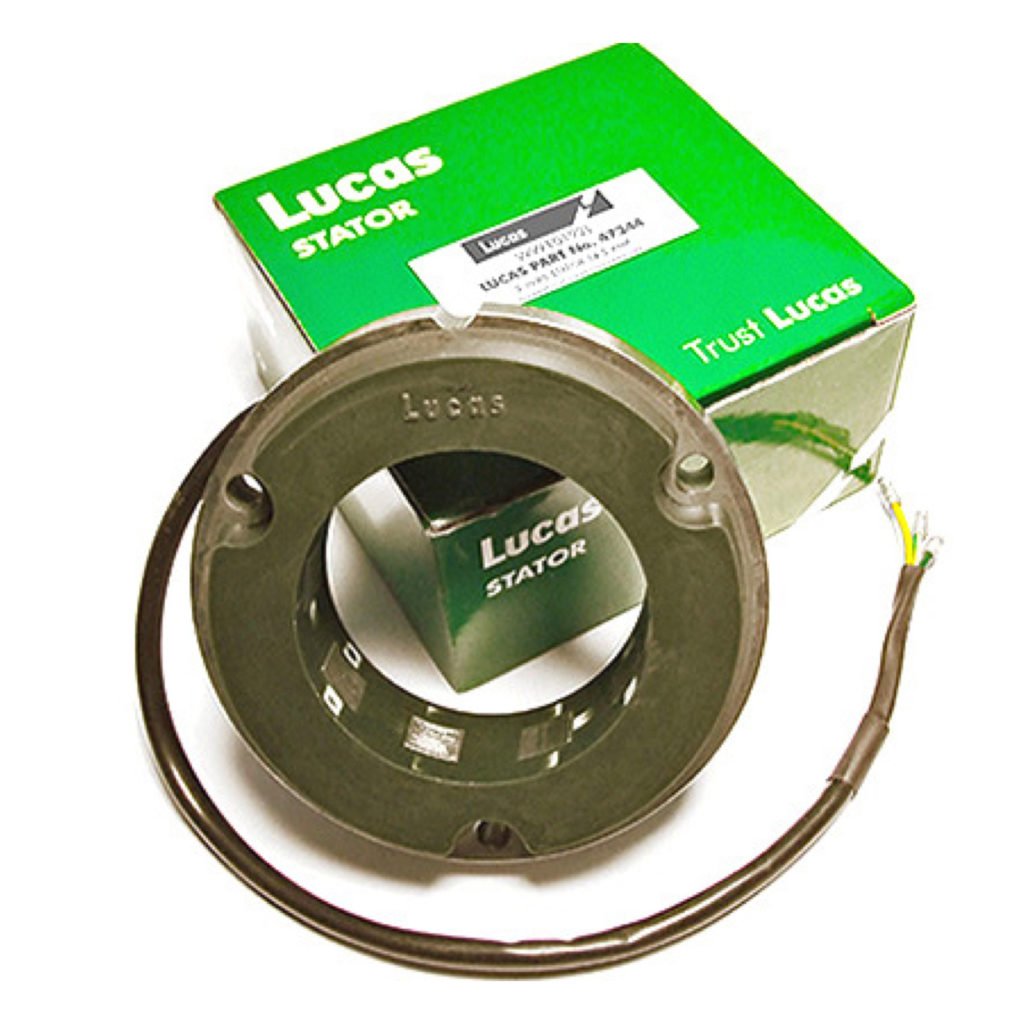
You’d be forgiven if you found the many Lucas alternator variations confusing, the RM (Rotating Magnet) alternator dates back to the 1950s, and became the standard alternator used in many British motorcycles, but during this evolution there were many changes made. The majority of these alternators were six-pole, single phase, but the final version Lucas introduced in the late 1970s, was a 3-phase stator, distinguishable by its 9 poles (shown right).
The first model produced was the RM12, and featured a hexagonal frame. During this period Lucas experimented with various designs to boost power output, resulting in multiple variations as they refined the alternator. The RM13 introduced a round frame and a slightly higher output, while the RM14 reverted to the hexagonal frame. Next came the RM15, which also featured a round frame. This was to be the final model in this series that used the smaller, 70mm rotor. These alternators produced approximately 60 watts of power and had 6, 4 and 3 wire options.
In the 1960s Lucas introduced the RM18 which used a new larger diameter, 74mm rotor, the now familiar round frame with open windings, and three wires, which had become the standard format. The new unit produced around 100 watts of power. The mounting holes remained the same pattern and spacing as the RM13 making it interchangeable with the earlier round frame versions. The RM19 soon followed, this was intended for 6V operation, produced more power and featured encapsulated windings to prevent failures from engine vibration. The RM19 produced about 120 watts of power and originally had been destined for use on motorcycles that had two-way radios but soon became standard equipment on most. A further increase in the number of laminates in the stator gave the RM20 version, this was again a 120 watt output, but designed for larger engines running at lower revs, this was also the last of the three wire, 6 Volt alternators.
It is interesting to note that in the search for more output, and to give more power at lower engine revs, the number of laminates was increased. It is the amount of iron in an alternator that has a large bearing on its output, for this reason it is rarely possible to increase an alternator’s output by simply rewinding it with more turns of copper winding wire.
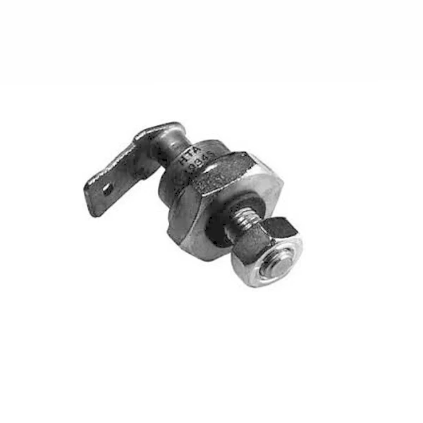
The development of the zener diode in the 1960s allowed 12 volt alternators to be used. The 2 wire RM21 stator gave 120 watts of power and came to be known as the ‘standard’ output stator. Then followed the higher output RM23 and RM27 stators, which also had 2 wires. While the zener diode represented a large improvement, it was still a very crude way to control alternator output. Two were needed to dissipate the full output power, these had to be closely matched to ensure identical zener voltages. A lesser known feature of the zener diode is that as it heats up, so the voltage it regulates at increases, it can get to nearly 16 volts, over charging the battery considerably.
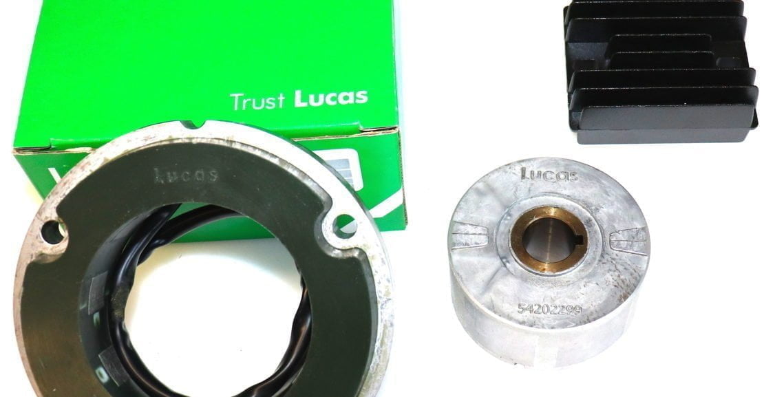
The 1970s saw the arrival of a 3-phase stator to the Lucas catalogue, the RM24. This stator used the same 74mm rotor and mounting pattern as earlier versions and can be identified as it has 9 poles. The advantage of a 3-phase alternator is that far more power is available lower down the rev range, a feature that is extremely useful for town riding or slower revving engines. The RM24 was intended to quickly recharge batteries on electric start motorcycles, however Lucas then produced a lower output version of the RM24 for non-electric start models. Lucas created further confusion by using the same wire colours as the 6 volt, 3 wire units on these 3-phase stators.
The original 6-volt, three-wire alternators are no longer made. This system had no voltage regulation other than an attempt to reduce overcharging by manually switching on or off sets of the alternator coils based on the headlamp switch position. This unregulated 6-volt system also relied on a large, wet lead-acid battery to hold the voltage at 6 volts, this works to a degree but only when the battery is fully charged. Power surges as the engine is revved or when the headlamp is switched could reach dangerously high levels and batteries were often left boiling by excessive charging. In today’s world it is deemed completely unacceptable to sell such a system.
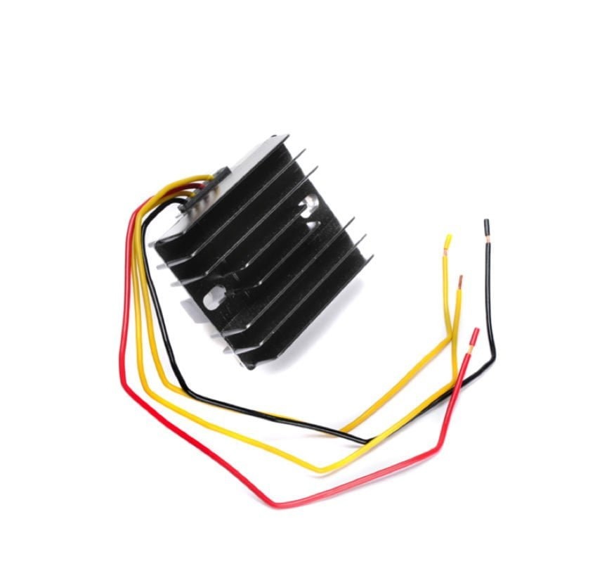
For those wanting to up-grade the RM18 (and later versions) a solid-state regulator rectifier represents possibly the most significant up-grade possible. The rectifier, fitted as standard to the bike has no regulation function. A regulator rectifier simply connects between the stator and bike’s wiring, at the old rectifier connections for example, with no need to disturb the connections at the headlamp, ignition switch or ammeter. We deal with what connections to make in the fitting guide for the voltage regulator, as this is outside the scope of this blog.
At Rex’s Speed Shop we offer hand-picked regulator rectifiers that easily handle the power output, in both 6V and 12V versions, however, it is not recommended that the high output 16 amp stators, nor the 3-phase RM24 be regulated to 6 volts. The windings in these are highly optimised for 12 volt operation and they become heavily self-regulated with excessive current demand, which is a natural feature of all alternators to protect their windings from excessive current flow within them. A 6 volt system demands twice the current of a 12 volt one, so the result is that the output from a 12 volt alternator rapidly becomes reduced if you regulate it below its design voltage.
Eight Tips For a Reliable Lucas Alternator Charging System
- Early systems using 70 mm rotors do not have sufficient output to be used with regulator rectifiers, also many rotors have lost magnetism by now, further reducing their output. The only realistic option is a new replacement alternator. Hexagonal RM12 &14 stators also require an adaptor to allow a round RM21 to be fitted to the engine, at the time of writing we are not able to supply such adaptors.
- The later 6-volt RM18, RM19, & RM20 alternators can be regulated to either 6 or 12 volts with a solid-state regulator rectifier. This is a different piece of equipment to the rectifier that was fitted as standard and will prevent overcharging in either voltage. Motorcycle electrical systems perform much more efficiently at 12 volts so if you are at this stage it is well worth the extra effort to convert the bike to 12 volt operation.
- If you’re planning to install electronic ignition while maintaining a 6-volt electrical system, it’s essential to use a 6-volt solid-state regulator rectifier. Most electronic ignitions will not tolerate the power surges of an unregulated system and manufacturers will void the warranty if the ignition fails and no voltage regulator is in place. Therefore, we suggest that a regulator rectifier is a must, and not an option.
- If you want to run without a battery, use either a high output RM23/27 or the high output 3-phase stator. These will allow the engine to start and run with no battery, provided a capacitor (battery eliminator) is fitted in place of the battery. This works in lieu of the old ‘Emergency’ selection also allowing the engine to run normally. Be aware that this is a very crude system, so lights may flicker and the horn will not work correctly with the engine at idle, also if the engine stops you are left with no lights. We recommend road bikes are fitted with a battery, especially where LED lights are fitted.
- Replace zener diodes with a modern regulator rectifier. A Zener diode regulated system has a natural tendency for the regulated voltage to rise as the diode warms up. This can reach a level that will damage modern electronics and batteries. Large power surges are also caused as the diode reaches its zener voltage and begins to conduct. Additionally the zener diode is connected in such a way that should it become disconnected or fail, the charging system will receive the full un-regulated alternator output, almost certainly electronic ignitions, modern batteries, LED lights or any accessory connected to the bike’s electrics will be damaged by such an event.
- An AGM battery will hold a charge for a very long period of time and can be left unused with little ill effect, providing they were fully charged before being left standing. Cyclon batteries have an even longer design life, but AGM batteries such as the yellow Motobatt are also held in high regard with owners due to their stable nature. A voltage regulator must be fitted when using modern, sealed batteries, it is not optional.
- Avoid the lightweight lithium batteries, these are extremely reactive and have very exact charging requirements, that in our opinion, aren’t compatible with classic motorcycle charging systems. We receive a very high number requests for help from owners who were sold such batteries and now have serious (expensive) electrical faults to fix. Please note that MOSFET regulator rectifiers are designed to reduce the operating temperature of extremely high output motorcycle generators, those in excess of 30 amps. They offer no benefit or protection as far as Lithium batteries are concerned as Lithium batteries are extremely sensitive to incorrect charging.
- Check all wiring and connections are in good condition! This is an obvious one but we still see so many examples of inappropriate or end of life wiring causing faults.
Thank you for reading, if you have any questions please contact our technical team at Rex’s Speed Shop
Hi , will a RM stator kit fit a D1 BSA bantam that had a Lucas Alternator fitted originally, also where could i get an adaptor ? if its required .
Thanks
Mark